UGCS Analysis

The TerraMax UGV is controlled by a ruggedized operator control unit (OCU). This OCU enables the operator to monitor both systems of the vehicle as well as the status of the mission the UGV is conducting. The software, console and controller allows for the operator to control multiple systems simultaneously allowing the operator to quickly update the software to maintain the operations tempo (optempo). There is not much information on the specific control unit of the system on the internet but from the looks and form factor it appears to be nothing more than a ruggedized tablet with quick select buttons that run long both sides of the tablet. The controller appears to resemble an Xbox gaming controller with various buttons and knobs. The design appears to be a quick design platform to a UGV design that more than likely will require a more robust solution if such a vehicle is to be utilized in large numbers within a given area of operations. With this said, there are companies designing ground control stations that are capable of managing ground vehicles such as the universal ground control station by Textron. As a result of the interoperability standardization set forth through STANAG 4586 and standardized message formats and interfaces that can be shared with other systems all types of unmanned systems can utilize this specific setup in the UGCS. According to Textron the UGCS architecture provides command and control capability for UAS as well as UGV and USV systems. (Defense Update, 2009). The UGCS is designed for ease of use between systems as well as for the ability to maintain situational awareness of the operators. According to Textron, the system incorporates a modular hardware and software design that is easily scalable and is easily reprogrammed for different unmanned vehicles (Textron, 2015). When entering the UGCS one will quickly notice the design setup is user friendly and ergonomically set up with comfortable seating and large, easy to read screens at the workstations. This is much different than the original control stations from the late 90’s with multiple screens supplying varying degrees of information which have been the result of numerous instances of situational awareness loss. One possible update to future systems might be the use of pilot/operator sensor integration to supply the senses for enhancing the situational awareness that is currently missing as a result of being removed from the aircraft.

References
Textron. (2015). Universal capabilities for the next generation battle space. Retrieved from http://www.textronsystems.com/sites/default/files/gallery/TS%20US%20UCGS%20Datasheet.pdf
Defense Update. (2009). AAI offers multi-uas integration with STANAG 4586 compliant ground control ‘one system’ GCS. Retrieved from http://defense-update.com/products/o/onesystem_4586.html
DJI S1000 and Blackout Mini-H builds

DJI S1000:

The above system is one built by the user for custom applications and not a system that is out of the box ready to fly. With this being said there are several possible options for the system as it relates to the mission intended. For this mission a build giving the system a medium range using a radio link AT9 transmitter with a RD9 receiver will enable the system to travel out 650m and easily cover the 400AGL requirement. The system will utilize the DJI NAZA A2 flight controller with intelligent orientation control and banked control mode (DJI, 2015). The A2 comes with both the power management unit (PMU) and the inertial management unit (IMU), GPS and a dual can bus to plug in the needed sensors and gimbal. The A2 will interface with the IOSD MARK II which will record real time flight data of the system and transmit to the ground station via the 2.4 GHz digital video downlink (DJI, 2015). This important information about the internal state of the system will enable the user to ascertain the flight parameters and health of the overall system such as battery amps, mah, pitch, roll, airspeed and altitude (DJI, 2015). The S1000 will carry the zenmuse Z-15-5D 3-axis professional gimbal with internal IMU and infrared module and will house the 22.3 mega-pixel Cannon 5D Mark III camera capable of both still photographs and high definition video at 1080p (Cannon, 2015). The gimbal, with 3 axis rotational control, will be mounted directly under the center of gravity of the copter instead of rails located on the front side of the octocopter thus potentially destroying flight characteristics. The S1000 will utilize the folding gear so the sensor and gimbal can one, move freely and two have a 360 degree unobstructed view. In order to get the highest quality shots and video possible the digital downlink will provide FPV through the airframe mounted video camera. This system was chosen because of its ability to carry a heavy load including all components as well as the camera/sensor. The fact the S1000 comes with folding landing gear adds to the ability to have clean and clear shots and less post production development.
FPV Racer: Black Out Mini-H
The black out mini-h is an h frame quad copter. This quad is built to go fast and due to its size only will carry the a 3S battery, lumenier 12A ESC’s and 2300kv engines, Tyranis X9-D transmitter, Acro Naze 32 flight controller, and a small receiver that can also supply telemetry (battery amps, mah, percentage left) information to the transmitter. The FPV kit is the Fat Shark teleporter V3 which comes with the 5 mega-pixel fixed position HD camera, with SD feature, that will be mounted in the nose of the quad, the 250MW with linear dipole antenna, and the FPV goggles. (FatShark, 2015). This system was selected because of the ease of construction as well as the ability to utilize the sensor/FPV kit that has been tested and proven to work. With this build it’s important to keep the system light so there was no need to use sophisticated components with lots of bells and whistles other than the sensor/payload.

REFERENCES
Cannon. (2015). EOS 5D Mark III. Retrieved from http://shop.usa.canon.com/shop/en/catalog/eos-5d-mark-iii-body?utm_source=bing&utm_medium=cpc&utm_term=+Canon++EOS++5D++Mark++III&utm_content=B_Search_Brand_EOS%205D%20Mark%20III%20Body_BMM&utm_campaign=B_Cameras_Search_Brand_EOS_BMM&cm_mmc=BI-_-CameraGroup-_-140911Brand%20Paid%20Search-_-Canon%20EOS%205D%20Mark%20III&Ap=EOS%20Cameras
DJI. (2015). Spreading wings S1000. Retrieved from http://www.dji.com/product/spreading-wings-s1000
FatShark. (2015). Teleporter V3 rtf fpv kit with hd camera. Retrieved from http://www.fatshark.com/uploads/pdf/1756-2.pdf

ICARUS Unmanned Search and Rescue

The ICARUS unmanned search and rescue project, a European Union project, has developed a system that incorporates both aerial unmanned systems and maritime unmanned systems in an effort to conduct search and rescue (SAR) in the maritime environment (Icarus, 2012). The U-Ranger is a CMRE/L-3 built unmanned system that was used in both the testing and demonstrations conducted by the ICARUS project. The system is designed based on the MOOS architecture to utilize certain behavioral patterns such as situational awareness, area search, track-and-trail, obstacle avoidance, station keeping and waypoint routing. (Icarus, 2014). In order to achieve this the system uses a combination of proprioceptive and exteroceptive sensors to conduct the SAR mission. U-Ranger uses and onboard computer/control unit to process all commands such as communications with the USV, acquiring exterocpetive sensor data for processing in system control and GPS guidance. The USV utilizes an Airmar ultrasonic weather station, an exteroceptive sensor, with an internal compass and onboard WAAS/EGNOS GPS to gather information on true wind direction, atmospheric pressure and air temperature which is then sent to the onboard computer for processing and to the onboard navigation system (Icarus, 2014). Connected to the CMRE front junction box and sensor interface power distribution where the sensors interface with the rest of the system. The internal measurement unit, a proprioceptive sensor, utilizes 3-axis accelerometers, gyroscopes and magnetometers to measure the U-Rangers velocity and orientation (Icarus, 2014). The U-Ranger also uses a gyro-stabilized thermal camera with 640×480 resolution 360 degree continuous pan with a daylight camera included (Icarus, 2014). This exteroceptive sensor is utilized predominately for searches in the water. Also connected to the junction box/power distribution is the laser range finder, a combination exteroceptive proprioceptive sensor depending on the certain requirements. Typically this device is used to by the onboard computer to adequately navigate obstacles located around the U-Ranger in hostile environments. Multibeam sonar is utilized for acoustic sensing for underwater surveillance and reconnaissance.

The ICARUS project has tested both the USV and fixed and multicopter unmanned systems together in a simulated demonstration. The first part of the demonstration shows the need to find the victims quickly using a fixed wing unmanned aircraft loaded with an EO/IO sensor video camera to locate the victim. Once identified and assessed an octocopter can sent to make further evaluation as well as drop, if needed, supplies such as life jacket and water. The U-Ranger will then deploy to the victims attempting the rescue by deploying a small boat that will make further contact and deploy a self-inflating raft. These systems have the capability to be deployed quickly and get to the victims in a timely manner whereas manned assets will most often take longer periods of time to do so. However, the combination of unmanned and manned systems working together will have a greater impact of the lifesaving abilities of search and rescue teams.

REFERENCES
Icarus. (2014). Integrated components for assisted rescue and unmanned search operations. Retrieved from http://cinav.marinha.pt/PT/Avisos/Documents/7_Comunica%C3%A7%C3%A3o_Prof_An%C3%ADbal_Matos.pdf
Icarus. (2012). Project overview. Retrieved from http://www.fp7-icarus.eu/project-overview

How the Predator works

How the Predator works.

There is plenty of information on the internet about the MQ-1 and other variants of this aircraft. Whether or not the information provided is completely accurate may be a different story entirely. This article covers the MQ-1 from nose to tails and everything in between in some detail. Of importance and multi-spectral targeting system (MTS) relevance to USNY 605 is the multi-spectral targeting system or MTS sensor. The MTS is an exteroceptive sensor manufactured by Raytheon and has been through several iterations as a result of technology advancement and upgrades to the MQ-1 and other variants. (Valdes, 2015). This sensor is comprised of a turret that mounts on the underside of the aircraft. This ‘ball’ is gyro-stabilized and incorporates a day TV camera, a low light tv camera (LLTV), laser range detecting (LRD) and laser target marking (LTM) (Valdes, 2015). In addition to this sensor the system utilizes Hellfire missiles and uses the onboard computer to make calculations as to trajectory and distance to the target (Valdes, 2015). Other sensors bundled into the MTS also calculate wind speed, direction and other variables in order to fuse the data together for a firing solution (Valdes, 2015). The article also goes into some depth on locations and implementations of other sensors both exteroceptive and proprioceptive. The diagram provided by the author shows the locations of the Ku dish, synthetic aperture radar (SAR), global positioning system/inertial navigation system (GPS/INS) and other sensors that provide information to the system about the current condition of the environment (Valdes, 2015). A good example of this is the ice detection sensor located on the fuselage of the aircraft. A further example of the proprioceptive sensor is the angle of attack (AOA) sensor that provides the autopilot system important information as it relates to its positioning.
REFERENCES
Valdes, R. (2015). How the predator uav works. Retrieved from http://science.howstuffworks.com/predator.htm

UAS RFP

Jason B. Heyman
ASCI 530
Activity 7-4
27 September 2015

Natural disaster recovery and support by unmanned systems is a mission and role that will increase in the very near future. As a result many types of ground and aerial systems will be designed and utilized. A highly versatile system will be capable of being utilized in support of different types of natural disasters such as forest fires, hurricane, tornado and other homeland security missions such as low level support for law enforcement and explosives detection. This system design will incorporate a flight control system and sensor system capable of being hot swapped between airframes in order to support differing types of natural disasters. For example, a forest fire may require the system to be man packed to an assembly area where the fire is burning on all sides requiring a system to be capable of vertical takeoff and landing (VTOL). A mission of tornado surveillance and recovery operations would, likely, require a system capable of longer duration flight in order to cover larger areas of destruction. This may require and be better suited to an unmanned fixed wing aircraft. This system is called the hybrid raptor and will take 3 years to develop.

1. Air Vehicle Element
1.1 –Air vehicle fixed wing shall possess an 11.5 horsepower 2-cyl gasoline powered engine capable of producing enough power to weight ratio to support altitudes needed for mission effectiveness.
1.2 – Air vehicle quad-copter shall possess 24v electric motors capable of heavy lift operations.
1.3 –Air vehicle fixed wing shall possess a muffler system capable of spark arresting as well as sound mitigation.
1.4 –Air vehicle fixed wing shall possess a large 1000cc gas tank to support required operations.
1.5 – Air vehicle quad-copter shall possess 2 x 5500mah 4s batteries to supply enough energy and power.
1.6- Air vehicle fixed wing shall be man packable and capable of being assembled and ready for flight in 15 minutes.
2. Command and Control.
2.1- The system shall incorporate a flight control system for manual and autonomous flight and swappable between fixed and rotary winged aircraft.
2.2- The command and control (C2) system shall be redundant flight control systems to prevent system failures of the flight control system which may lead to system loss.
2-3- The C2 system shall utilize a software graphical user interface (GUI) for depiction of operational and emergency mission sets as well as depict the exact location of the systems in flight through use of the GPS coordinates and telemetry in the downlink of the RF frequency communications.
2-4. The C2 system shall visually depict the video from the sensors onboard the aircraft.
2-5. The C2 pilot video shall be encoded and compressed for transport through the RF frequency downlink to the ground control station.
2-6. The C2 pilot video shall be reassembled through use of a decoder and then projected to the sensor operator’s workstation.
3. Payload
3-1. The Air vehicle shall incorporate a swappable between airframe system capable of providing medium wavelength infrared (MWIR), daytime camera and night time IR. (Trillium, 2015)
3-2. The daytime camera shall provide 80 degrees field of vision (FOV).
3-3. The sensor shall provide the ability to adjust both iris and FOV.
3.4. The sensor shall provide 4x magnification
3.5. The sensor shall provide laser range finding.
3-6. The sensor shall be environmentally sealed to protect cameras weather.
3.7. The sensor shall incorporate a heated camera lens.
3-8. The sensor shall be gimbled.
3-9. The sensor shall incorporate GPS/INS for geopointing and geolocation.
3-10. Sensor shall utilize on board aircraft power.
4. Datalink.
4-1- The visual line of sight (VLOS) datalink shall maintain 2 mile plus contact with base station.
4-2. The uplink/downlink shall be replicated by a total 2 x transmit (TX) and 2 x receive (RX) to provide redundancy.
4-3. The uplink/downlink shall be connected at all times to both TX and RX.
4-4. The system shall switch between TX1 and TX2 every 500ms.
4-5. The system shall switch between RX1 and RX2 every 500ms.
4-6. TX 1 and RX 1 shall be located on the underside of the aircraft.
4-7. TX 2 and RX 2shall be located on the top of the aircraft.
4-8. Uplink shall provide 1000 kilobits per second (kbps) data rate for communications.
4-9. Downlink shall provide telemetry information through one of the RX links per selection at a rate of 5mbps.
4-10. The sensor (sensor ball) shall provide interleaved and compressed video through the encoder to the GCS where it will be de-interleaved and de-compressed at the decoder and piped to the workstation for viewing.
Testing Requirements.
1.1 Air Vehicle.
1.1.1. Bench test gasoline engine to produce to specific parameters.
1.1.2. Bench test electric motors and batteries to specific parameters.
1.1.3. Test muffler and spark arrestor with gasoline engine.
1.1.4. Test 1000cc gas tank to ensure proper fit and function with engine.
1.1.5. Test batteries with electric engine and examine voltage and durability.
1.1.6. Test with pack and time for assembly.
1.2 Command and Control
1.2.1. Test the system in both configurations to ensure its ability to be moved rapidly between airframes.
1.2.2. Test the duplicate modules/system for redundancy and failover.
1.2.3. Test emergency mission and operational mission setup on the GUI.
1.2.4. Test projection of video on heads up display.
1.2.5. Test interleaving and compressibility between encoder and decoder for transport through RF links.
1.3. Payload.
1.3.1. Test functionality for swap of the MWIR ball between airframes.
1.3.2. The daytime TV rotates to provide 80 degrees FOV at resolution 1024.
1.3.3. Test functionality of Iris and FOV
1.3.4. Test zoom of sensor ball to 4 x magnification
1.3.5. Test laser in secure location with boresight table and range.
1.3.6. Test seals on ball to ensure safety from weather.
1.3.7. Test lens heat with iced over lens.
1.3.8. Test functionality of gimbal with strategically placed targets. Rotate and ensure ball is stable.
1.3.9. Test georeferencing and GPS systems with ball
1.3.10. Test aircraft power supplies with gimbled ball.
1.4. Data Link
1.4.1. TX/RX must maintain connectivity with ground base antenna for greater than 2 miles.
1.4.2. Test antennas for power, gain and attenuation.
1.4.3. Test uplink and downlink for the ability to pass traffic.
1.4.4. Test handoff between TX 1 and TX 2.
1.4.5. Test handoff between RX 1 and RX2.
1.4.6. Test communication between TX 1 and RX 1 on bottom of the aircraft in different configurations of flight.
1.4.7. Test communication between TX 2 and RX 2 on top of the aircraft in different configurations of flight.
1.4.8. Test uplink at 1000 kbps to failure with data push of preconfigured packets.
1.4.9. Test downlink at 5mbps to failure with data push of preconfigured packets.
1.4.10. Test compressibility and assembly of the data from sensor to the encoder on the aircraft, downlink then decoder.
Table 1: time frame development schedule
Phase Timeline
Initial Investigation 1 August, 2015- 1 January, 2016
Requirements Definition 1 January, 2016- 1 May, 2016
System Design 1 May, 2016- 1 April, 2017
Subsystem Development/Procurement 1 April, 2017-1 December, 2017
Subsystem Test 1 December 2017- 1 1 February, 2018
System Test 1 February, 2018- 1 April, 2018
Initial Operational Capability/ Implementation 15 April, 2018
Subsystem Redesign 18 April, 2018-1 June, 2018
Subsystem Test 1 June, 2018- 15 August, 2018
System Test 16 April, 2018- 1 August, 2018
Full Operational Capability 2 August, 2018
Maintenance 2 August, 2018- system life span

The development process chosen is one which many UAV manufacturers use; a requirements based process (Micropilot, 2013). Requirements based is also linked to quality control as a result of low-level bullet points spelling out the design. This process and methodology address the concerns UAV manufactures face when designing their products (Micropilot, 2013). These requirements based processes describe functionality of the designs while explaining the information to the non-technical design members such as those in marketing departments. (Micropilot, 2013). Because these systems are airborne and have the potential to create dangerous situations when they fail designers have a large incentive to not let things slip through the cracks. Therefore, having specific high level requirements allows for the creation of a list of items that describe what is needed at the technical level in order to complete the actual design of the system feature. (Micropilot, 2013). As stated previously, Quality control (QC) is a large piece of requirements based development and supports the team’s efforts in QC to verify their plans and implementations match what the system is meant to accomplish. (Micropilot, 2013).
Testing strategies used are component level, subsystem and integration of systems. Once these are complete and bench tested to standard the system will boxed and shipped to Grand Forks, ND test site. This site offers large flat expanse to test RF, VLOS, uplinks/downlinks, operational and emergency missions. The test preparation will take place in several phases with the first being the operational and emergency mission bench test followed by a software simulation test. Once passed it will be flight tested at less than ½ NM from the GCS to ensure VLOS functionality. Once complete to standard the VLOS test up to 2NM range will be conducted. Once verified the system maintains VLOS and communications the operational and emergency mission profiles will be tested. Once to standard the system will be placed lost link invoking the emergency mission profile and loiter. Upon successful entry into loiter both TX/RX will be placed in high power to be verified and then the GCS power will be turned back on to capture the aircraft and safely land.
A system that is capable of both fixed wing and rotary wing operations is one that will enable emergency management to readily and quickly adapt to a number of differing natural disasters. The ability to fly the rotary wing UAS in mountainous regions looking for a missing person is different than conducting the same mission in low-land flat areas that require a longer search pattern which may require longer flight time. By utilizing this flight control system the users of the systems will have the peace of mind they have the equipment on hand to meet the needs of the many situations giving them the tools to be successful no matter set of circumstances. Therefore, the design requirements listed attempt to cover the propulsion systems, power systems, command and control, payload and the corresponding testing items.
The cost of the flight control system is the major cost with each purchase consisting of the swappable flight control and autopilot, and the ground control element including data links. The cost of the system is $5,000 for just the control system. The quad-copter and fixed wing aircraft can be purchased separately but are not required.

References
Hobby King. (2015). Turnigy TR-111 111cc twin cylinder gas engine 11.5 hp. Retrieved from http://www.hobbyking.com/hobbyking/store/__42068__Turnigy_TR_111_111cc_Twin_Cylinder_Gas_Engine_11_5HP.html
Loewen, H. (2013). Requirements-based UAV design process explained. Retrieved from http://www.micropilot.com/pdf/requirements-based-uav.pdf
Trillium Engineering. (2015). Orion HD80. Retrieved from http://w3.trilliumeng.com/orion-hd80-documentation.html

UAS Missions

Jason B. Heyman
ASCI 530
Activity 6-4
18 September 2015

UAS Mission

Unmanned aviation systems (UAS) can be utilized in a variety of missions in both civilian and military applications. The use of UAS in the field of forestry specifically forest fire will be one in which these systems may have a significant role. Every year in the United States there are thousands of forest fires. So far 2015 has seen a total of 46,474 fires burning 8,821,040 acres of land. (National Interagency Fire Center, 2015). There are hundreds of companies that specialize in air attack utilizing slurry bombers to assist ground crews in battling the fires. One of the mission sets for these groups is intelligence, surveillance and reconnaissance role (ISR) or fire spotting. This is conducted by a number of different aircraft, but the one that I’m intimately familiar with is the King Air C90. These aircraft are not inexpensive to operate and require refueling often. The aircrews also have specific requirements that must be met throughout the work cycle. This is a role and mission that could be conducted by a UAS with a specific design. Three possible systems are the Octotron SkySeer, the MQ-1 Predator and the small quad-copter UAV.
In 2007, the United States Forest Service (USFS) purchased two Sky Seer unmanned aircraft systems (UAS) with the intent to test them for specific operations. Due to the regulatory climate at the time the USFS benched the $100,000 systems (Gabbert, 2013). No information has been found recently on the USFS website that would indicate they are currently using these systems although a number of government entities now possess certificates of authorization to either test or utilize these types of systems (Jeffrey, 2012). Due to its 2 mile range, the Octotron Sky Seer would be a good short range system for missions such as small fire support and reconnaissance and use by hot shot crews and slightly larger units. The SkySeer weighs in at 5lbs, is quiet due to its electric motors and can be assembled in minutes (Johnson, 2013). It is a hand launched platform that is small and compact enough that it can be man-packed not creating an issue for already overload crew members. The system has a flight time of up to 70 minutes depending on power supply and sensors incorporated into the aircraft (Johnson, 2013). It is recoverable by deploying a parachute or landing traditionally given space available (Johnson, 2013). Just like most systems, this one can be controlled autonomously through the use of global positioning systems (GPS) and the use of software based graphical user interface (GUI) that a user can input waypoints and allow the system to fly. Furthermore, the system is capable of recording video from sensors on either a thumb drive or a DVD via the ground based station (Johnson, 2013).
A second system capable of larger fire support is the MQ-1 Predator. Due to its size, fuel requirements and payload capacity this system would be available to provide up to 24 hours of coverage and ISR, full motion video support for crews battling large coverage wild fires (DOD, 2015). Although this is system is by far out of the price range for small fire departments it could be available to crews on a temporary basis on loan from other branches of the government. During the Rim Fire at Yosemite in 2013 the California Air National Guard provided support flying missions with the MQ-1 (Gabbert, 2015). This system can carry a number of sensors but the organic cameras and assets include, ‘the ball’ which is capable of laser range finding, day and night tv viewing, infra-red sensing and more (DOD, 2015). This could prove to be indispensable to fire support in any type of fire situation. The ability to see a hot spot before it flares can provide commanders the ability to direct ground crews to extinguish it (California Air National Guard, 2013). The system is a long range asset and one that wouldn’t be maxed out due to the size of the fire. In addition to full motion video it may also be a good choice for fire marking providing tanker after tanker the ability to drop retardant or water for multiple hours at a time. The locations of targets, in this case the fire, can be updated to the tracker software in the form of reference points giving both the operators, manned systems and ground personnel good situational awareness as to the status of both the fire and the equipment.

The pilot and the sensor operator can use the autopilot systems and the operational mission planning software to place the predator in a long term loiter over a fire giving the incident commander (IC) eyes on the objective for up to 24 hours at a time (DOD, 2015). The system can also support remote terminal viewing that can be sent to approved screens possibly ones that crews can utilize in the field to help them determine fire lines (DOD, 2012). One of the challenges of utilizing this system is the cost of employing it, and if not an organic asset, the ability to acquire its use through other governmental agencies may be difficult; however, it proved its worth in the Rim Fire of 2013.
If you conduct an internet search for a multi-copter used for firefighting you will see numerous returns for many systems that have been used to aid firefighter but no real systems that have been developed for such a role. Multi-rotor systems may prove to be a reliable system for the role due to the fact they can land and takeoff vertically in tight spots; a situation in which firefighters may find themselves. Indoor firefighting doesn’t provide space enough to operate fixed wing, but may be suitable for small quadcopter type assets. These same quad or hex copters could provide fire fighters the ability to reconnoiter the outside structure of a building prior to laddered assets arriving on scene. Their use may also keep firefighters out of dangerous situations while conducting searches. The use of a cheap system such as the DJI phantom may provide eyes on hard to reach places quickly enabling the IC to make timely decisions, but it may not stand up to high temperatures a fire could produce. Students at Utah’s Weber State University have developed a firefighting UAV that attempts to fix the issue of communications issues surround line-of-sight that often hinder real-time firefighting intelligence (Weber State University, 2015). The system utilizes a FM repeater for these types of operations that happen in the Rocky Mountain regions. (Weber State University, 2015). Another issue surrounding these types of UAV is the limited flight time. Students have also incorporated a tether able cable system that will allow the multicopter to stay aloft for up to 8 hours. (Weber State University, 2015).

REFERENCES
California Air National Guard. (2013). Predator plays critical role in rim fire fight. Retrieved from https://www.youtube.com/watch?v=u8IO4HbPvZc#t=152
Department of the Army. (2015). Technical Manual Operators Manual for MQ-1B Unmanned Aircraft System Warrior Alpha. Washington, DC: Government Printing Office.
Gabbert, B. (2013). Forest service not using $100,000 worth of drones. Retrieved from http://fireaviation.com/2013/12/04/forest-service-not-using-100000-drones/
Jeffrey, T. (2012). FAA has authorized 106 government ‘entities’ to fly domestic drones. Retrieved from http://cnsnews.com/news/article/faa-has-authorized-106-government-entities-fly-domestic-drones
Johnson, R. (2013). Orlando florida patrolled by surveillance drones as early as this summer. Retrieved from http://www.businessinsider.com/orlando-octatron-skyseeer-florida-surveillance-drones-2013-1
National Interagency Fire Center. (2015). National Preparedness. Retrieved from http://www.nifc.gov/fireInfo/nfn.htm
Weber State University. (2015). Firefighting UAV. Retrieved from http://www.weber.edu/COAST/Firefighting_UAV.html

UAS in the NAS

Separation of unmanned systems from current air traffic in the national airspace (NAS) can be done in several ways. First, no matter the size of the system they can be fit with transponders that are Mode C, S and ADS-B and GPS out which will give real time updates to ATC and other participating aircraft. These transponders are now small enough and light enough that allows for this to be a real possibility in just about any application such as small quadcopters and lighter than air. Sagetech makes one such system. http://www.sagetechcorp.com/unmanned-solutions/. This system can be incorporated on the UAS and a ADS-B receiver suctioned to the window on the airplane connected wirelessly to an IPAD will give you the locations of the participating aircraft. The UAS transponder as well as the aircraft mounted transponder will send out updates 2 x every second. (Sagetech,2015).

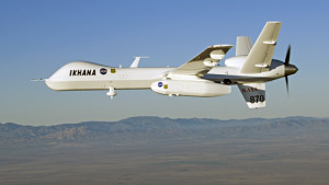
This, of course, is not a requirement of the FAA, yet and ADS-B/NextGen won’t be a requirement until 2020. (FAA, 2015). Manned aircraft currently use a variety of systems such as radar, TCAS I and II as well as the transponder. To answer the questions more specifically, yes, manned systems can be used on some forms of UAS. General Atomics and NASA have been testing the TCAS II, ADS B transponder, and the Honeywell due regard radar mounted on the NASA MQ-1B, Ikhana.

190779main_ikhana_pod_546

These systems take the information from the sensors and then route them through the onboard computer that utilizes specific algorithms which then maneuver the unmanned system away from other aircraft. (National Defense, 2015). According to the Department of Defense groups 3-4 accumulate the most flight hours (DOD, 2010). As a result of the systems usage and the fact this is a relatively new field; an observation would be that industry is going to create products for the most heavily utilized systems. The GA and NASA system is rather large and wouldn’t be utilized on a small group 1 UAS but could be on groups 3-5. Obviously, sUAS are very limited by weight and are often utilized at extremely low altitudes that often don’t require the same separation as do the higher altitudes with aircraft and systems on instrument flight plans. Of course this can be viewed as situation dependent where a sUAS operating near an airfield could be in the same vicinity as manned aircraft on takeoff or on final approach and in the direct flight path. Small unmanned systems operating VFR line of sight can be tracked via the transponder by ATC. As stated earlier, VFR pilots and UAS operators using ADS-B and an application such as Wing X pro or ForeFlight can receive accurate position reports thus aiding both the pilots aiding to situational awareness. However, systems small enough to provide autonomous aircraft separation such as the GA and NASA systems described above may be a ways off for group 1 and 2 UAS.

REFERENCES

Department of Defense. (2010). Unmanned aircraft systems. Retrieved from http://dtic.mil/ndia/2010psannualreview/TuesdayWeatherington.pdf

Federal Aviation Administration. (2015). Automatic dependent surveillance broadcast (ADS-B). Retrieved from https://www.faa.gov/nextgen/programs/adsb/

National Defense. (2015). General Atomics tests sense-and-avoid system. Retrieved from http://www.nationaldefensemagazine.org/archive/2015/February/Pages/GeneralAtomicsTestsSenseandAvoidSystem.aspx

Sagetech. (2015). XP family of transponders. Retrieved from http://www.sagetechcorp.com/unmanned-solutions/unmanned-solutions.cfm

UAV Systems Engineering

Here’s this weeks graduate school blog post.

Jason B. Heyman
ASCI 530
Activity 2-4
20 August 2015

Overweight: Systems Engineering Issue

Question: There are three (3) different discussion threads, based on the roles a Systems Engineer must play in the design process – 1) translator/intermediary between design teams; 2) “great decider” when there were conflicts between teams’ priorities or design considerations; 3) final authority on whether a complex system was ready for release. Pick a role (let’s try to mix things up and keep contributions in the three threads equal, please) and then write about a fictional UAS design situation where that specific Systems mindset or role would be needed. Once you have completed your thread contribution, please read a contributions from two of your peers (one in each thread) and provide your comments/response to what your peers wrote. Do you agree or disagree with them and why?

The project has saved 1.5 million dollars in both manpower and parts by utilizing commercial-off-the-shelf equipment for these two subsystems. The design process used is the iterative process. Iterative design is a design methodology based on a cyclic process of prototyping, testing, analyzing, and refining a work in progress. (Zimmerman,2003.). The issue now is the weights and distribution for guidance, navigation and control as well as the payload. During the mission analysis phase of the planning it was determined the need to utilize commercial-off-the-shelf system as a cost effective measure to keep research, design and software costs down. Mission analysis focused on the needs and requirements of the business as it relates to defining the problem or opportunity that exists as well as the constraints on boundaries of the selected system when it’s fielded. (SEBOK, 2015). What was not discussed was a limit to the weights and distribution between these two systems. This can be viewed as a misstep in the evaluation phase of numerous systems. During the preliminary design review (PDR) after requirements were generated the marketing department thought it would be in the best interest of the organization to market the system prior to completing the critical design review (CDR). The systems engineer’s responsibility is to bridge the gap between departments to act as a intermediary and make the decisions as to the overall direction of the project with responsibility to answer to management. Due to the marketing efforts there is a lot of interest in the designs as stated. As a result of this interest the design teams shall re-evaluate the commercial-off-the-shelf systems to determine if there is a better solution than what is currently in process. Once the review is complete the design team along with the Systems Engineer will develop three courses of action based on the systems chosen with respect to weight, dimension and overall usability. Based on the three courses of action the Systems Engineer shall make the decision to utilize the equipment showing the best promise of meeting the requirements of the PDR and the overall requirements from the mission analysis phase. The next generation systems, as a result of sales and real world testing, can be integrated with in house designed GNC and payload systems due to the fact that over the next ten years the airframe will not change as stated in the PDR. This will enable the R&D department to utilize funds on a yearly basis that are tagged for such development.

Systems Engineering Body of Knowledge. (2015). Concept definition. Retrieved from http://sebokwiki.org/wiki/Concept_Definition
Zimmerman, E. (2003). Play as research: The iterative design process. Retrieved from http://www.ericzimmerman.com/texts/Iterative_Design.html

AQM-34 role in current UAV/UAS design and technology

This morning as I drove to the airfield like I do on most mornings I was thinking about what I should write about in this week’s blog on an early design UAV/UAS. At that very moment I was crossing the intersection at Plant 42 I noticed the name of a street that I’ve passed dozens of times on this familiar route. Ryan Aeronautical Way. I had my answer.
Unmanned aerial vehicles of the pre-1970’s area were designed to conduct two missions. Reconnaissance and as an air to surface weapon both of which could, in theory, guide themselves to their intended target or named area of interest and execute command intent. Depending on the difference between the missions, one way or return, that system should be able to deliver itself to the target with accuracy or to return to a predetermined location and drop its reconnaissance payload and either crash, be recovered or self-destruct. (Mitchell Institute for Airpower Studies, 2015). Many designs had been tested during this time but the one that sticks most in my mind is the Ryan Aeronautical AQM-34 Firebee and the Israeli’s version, the 1241, bought for the 1973 Yom Kippur war. The Israeli’s, due to the purchase agreement, weren’t allowed to use the Firebee’s for certain missions in the current configuration so they changed it to perform recon and decoy missions. (Tulli, 2012). This version was modified to take off from a rail launcher using RATO (rocket assisted take-off) that would be jettisoned soon after separation from the rail. The systems was covered in radar absorbing paint and covers for the engine cowl installed to lower the radar signature. (Ambrosia, Wegner & Schoenung, 2011). The early US systems were recovered through the use of MARS (mid-air retrieval system) with the use of a hook, parachute and the helicopter. The updated Israeli version used a ground hook for retrieval much like the Scan Eagles retrieval system. During the war in 1973 the Firebees successfully evaded 32 of the missiles and destroyed 11 with their Shrike anti-radar missiles. (Ambrosia, Wegner & Schoenung, 2011). As a result the Egyptians fired their entire inventory of surface-to-air missiles at the Firebees—43 missiles in all. This mission was accomplished with no injuries to Israeli pilots, who soon swooped in over the depleted defenses. (Ambrosia, Wegner & Schoenung, 2011).

The Scan Eagle is similar in the reconnaissance intent and not so much the decoy piece. One can definitely draw parallels to the Firebee if for nothing more than LRE (launch and recovery element) and MCE (mission control element) as well as, possibly, the ground control. Early versions of Firebee were controlled from the launch aircraft a C-130. The 1241, after redesign, utilized a GCS (ground control station) of sorts and radar much like the predator family of UAVs which can be seen in attached YouTube video. (Tulli, 2012). The Firebee utilized a jet engine for propulsion whereas most, not all, systems today use either a normally aspirated engine or turbo-prop. The MQ-1 Grey Eagle utilizes a diesel engine, the MQ-9 Reaper a turbo-prop and the all new Avenger C a traditional jet engine. (General Atomics, 2015). It’s very evident that designs such as the firebee have influenced the designs of today. These systems also acted as testbeds for the low absorbable technology in the form of radar absorbing materials and paint created in the late 1950’s. (Richelson, 2015). In December 1971 the Air Force, after 9 months of testing and resolving issues, tested a Firebee with the new model 234 weapons system. The AV (air vehicle) was launched from the underbelly of a DC-130 via the microwave commanded GCS. After significant redesign of the systems which included the RPV flight control systems a newly designed weapons and launch system the Air Force tested an electro-optical missile utilizing a commercial grade video camera. This missile was successfully deployed off the rail of the Firebee and destroyed a simulated SAM missile site. (Quinty, 2015). Today, MQ-9 and MQ-1 systems launch hellfire missiles at military targets as a direct result of the testing conducted using the AGM-34 and 1241 Firebee. New technology of today will influence the designs of tomorrow most notably computing, autopilot systems, networking ability as well as sense and avoid in the national airspace.

REFERNCES

Ambrosia, V., Schoenung S., & Wegener, S. (2011) History of unmanned aerial systems. Retrieved from ftp://eco.arc.nasa.gov/pub/VinceA/Spain/

General Atomics. (2015). Predator C Avenger. Retrieved from http://www.ga-asi.com/predator-c-avenger

Mitchell Institute for Airpower Studies. (2010). Air Force UAVS: The secret history. Arlington, VA: Ehrhard.

Quinty, J. (2014). First Missile Launch & Direct Hit from a Drone-RPV: Firebee BGM-34A 1971 US Air Force-Ryan. [Video File]. Retrieved from https://www.youtube.com/watch?v=L9JIZa_meVU

Richelson, J. (2015). Science, technology and the CIA. Retrieved from http://nsarchive.gwu.edu/NSAEBB/NSAEBB54/

Tulli, Til. (2012). Teledyne Ryen 124I FireBee a reconnaissance jet UAV recovered in mid-air by helicopter. [Video File] Retrieved from https://www.youtube.com/watch?v=AV8jbGo2X68

Drone Flight Rules

Yesterday the FAA and DOT held a press conference…that’s right on Sunday! Do you think there is any pressure to get this going? Well, they are ready to release the notice of proposed rule making as it relates to commercial drone flights. Yep, it’s a major step for the FAA and for those hoping to use this technology for their business, legally. Basically the proposed drone flight rules suggest a new certificate for the operator by taking an FAA knowledge test (everyone even FAA licensed pilots must take this) to be allowed to operate safely in the national airspace. Also, you cannot operate above 500ft AGL and speed must be kept under 87 kts or 100mph. Furthermore, all operations will be conducted during daylight hours and in line of sight. This is absolutely a step in the right direction. The NPRM is currently listed here Soon, it will be listed on the regulations.gov webpage so that everyone who is interested in this proposed rule can make a comment as it relates to your personal thoughts on the rule. According to the rules the public comment will be available for 60 days from the date of posting. Please make your comments on this rule.

Here is the conference call. Thanks to Johnathan Rupprecht.

Jason Heyman is a single engine and multi-engine Commercial Pilot and Certified Flight Instructor/Instrument who has a passion for all things flight. He is currently working on a Master’s Degree in Unmanned Systems at Embry-Riddle Aeronautical University. If you wish to contact Jason please use the contact us page.